")

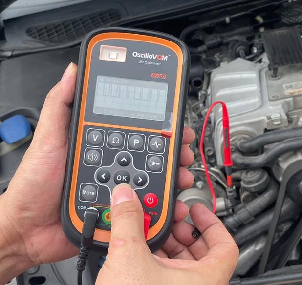
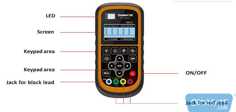
OSCILLOVOM OV300, released in 2023, is a handheld 2-in-1 digital tool for car and truck repairs. Combining an oscilloscope and multimeter with extra features, it enhances convenience and efficiency in diagnostics. Today, we will walk you through using its functions.
How to use OSCILLOVOM OV300 functions
- Voltage Measurement
After activating the device, press “V” to access the voltage measurement interface. The device features an automatic range and doesn’t require any adjustments. It’s specifically designed for measuring direct current voltage, offering a measurement range of -36V to 36V, an accuracy of±0.03V, and a resolution of 0.01V.
- Resistance Measurement
After activating the device, press “Ω” to access the resistance measurement interface. The device features an automatic range, eliminating the need for manual switching. The resistance measurement spans from 0Ω to 500KΩ, with an accuracy of±1%.
- Power Test
After activating the device, press “P” to initiate the power test function. This function evaluates whether the power supplied by the vehicle’s power line meets the required standards. Power can be tested within a range of 0 to 90W. OSCILLOVOM OV300 can automatically differentiate between voltages, provided that the tested voltage does not exceed 36V. Please note that power measurements should not be performed on the vehicle’s signal line.
- LED 0W Test Light: This function enables quick verification of the presence of electrical power, such as swiftly checking the continuity of fuses. If power is detected, the phrase ‘Power Detected’ will appear on the device’s screen, the LED will light up, and the buzzer will produce a continuous sound.
- 30W Test Light: This function primarily verifies whether the power line’s power can reach 30W. If the current is normal, the screen will display “Current Normal“, the test light will illuminate, and the buzzer will emit a continuous sound. In case of insufficient power, “Current Too Low” will appear on the screen, and the buzzer will sound an alarm. “90W test light testing” operates in the same manner.
- 5V/0.5W Power: This function primarily evaluates the power at the sensor‘s positive terminal. The test current is set at 100mA.
- Battery Voltage Drop Test at Startup
After powering up the device, click “more” and select the “Battery Voltage Drop Test at Startup” option. Now, connect the red test lead to the positive terminal and the blacktest lead to the negative terminal. Once you click “OK“, the multimeter will automatically initiate the test program. When “Please Start the Vehicle” appears on the screen, start the vehicle. Upon starting, the multimeter will automatically assess and provide a prompt if the battery voltage has dropped too low.
- Waveform Test
After powering up OSCILLOVOM OV300, press “![]() ” to access the oscilloscope function.
” to access the oscilloscope function.
Connect the red test lead to the line under test and the black test lead to the vehicle’s negative terminal. Throughout the test, OK functions as the pause/start toggle, ▲ and ▼ modify the displayed waveform, and◀ and ▶ adjust the displayed frequency.
- Continuity Test

This function is used to test the continuity of a circuit. If the resistance between thetwo test leads is less than 50Ω, the buzzer will emit a continuous sound, and thecurrent resistance value will be displayed on the screen, indicating a connection. Conversely, if the resistance exceeds 50Ω, the buzzer will remain silent, with only the current resistance value displayed on the screen.
- Illumination/Backlight
- This function illuminates the device’s screen. After powering on the device, press
 once to activate the backlight, and press it again to deactivate it.
 - To use the device’s LED light for night illumination, press and hold for one second. To turn off the light, press and hold for another second.
- Current Measurement Function
This function is primarily designed to measure the current flowing through a circuit. It can measure currents less than 3A with an accuracy of 1%.
Operation:
- Press
 and select “Circuit Measurement“.
 - As prompted, insert the black test lead into the COM (ground) jack, and the red test lead into the mA (milliampere) jack.
- Connect OSCILLOVOM OV300 in series with the circuit you wish to measure.
- Signal Output Function
This function supplies a voltage signal (ranging from 0.3V to 4.5V) to the vehicle’s ECU through the device, simulating the operational state of the corresponding sensor. This assists in determining the integrity of the vehicle’s relevant sensor and its circuit.
Operation:
- Press and select “Circuit Measurement“.
- As prompted, insert the black test lead into the COM jack, and the red test lead into the Sig jack.
- Use ▲ and ▼ to adjust the output voltage level, within the range of 0.3V-4.5V.
- Connect the black test lead to the vehicle’s negative terminal and insert the red test lead into the sensor’s signal wire. The ECU will then receive the signal voltage emitted by the device.
- Use ▲ and ▼to adjust the voltage level as required.
Whenever you encounter a problem operating OSCILLOVOM OV300, please refer to these detailed instructions to help yourself out!
OV300 Operation Video: